|
|


MODEL BROCHURE |
ELEVATION DRAWING |
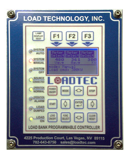
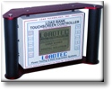
PROGRAMMABLE DIGITAL CONTROLLER (PDC) |
LOADLINK® DLL Interface for LabVIEW & WonderWare |
SAMPLE SPECIFICATION |
TECHNICAL DESCRIPTION |
GENERAL SUBMITTAL |
ADDITIONAL PHOTOS |
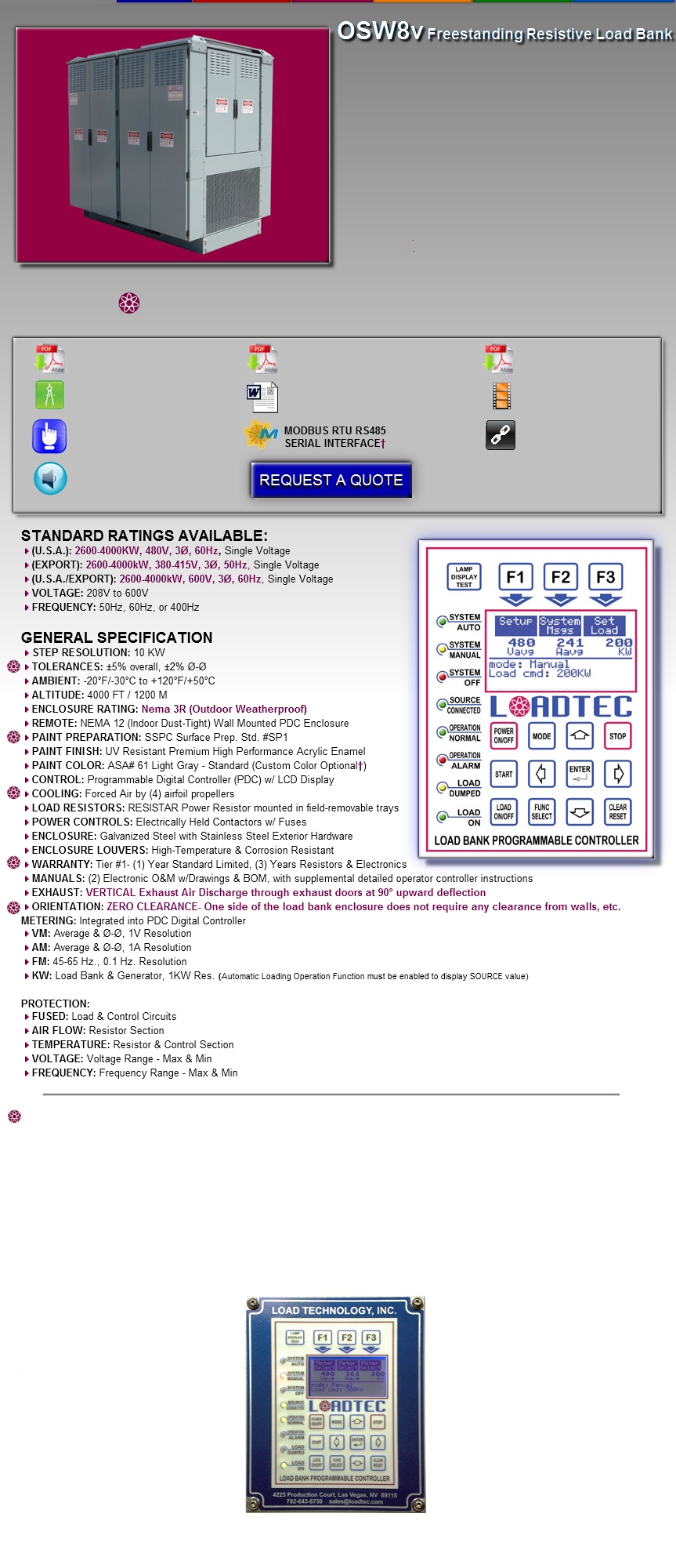
STANDARD FEATURES 42600-4000kW @ 480V or 600V, 3Ø, 60Hz 42600-4000kW @ 380-415V, 3Ø, 50Hz 410kW LOAD STEP RESOLUTION 4PROGRAMMABLE DIGITAL CONTROLLER (PDC) 4LCD METERING DISPLAY WITH KW, VM, AM, FM 4NEMA 12 REMOTE WALL MOUNTED PDC ENCLOSURE 4AUTOMATIC LOADING OPERATION* 4REGENERATIVE ABSORPTION CONTROL** 4AUTOMATIC EXERCISE OPERATION*** 4BASE LOADING & MANUAL LOADING OPERATION 4SELF-CONTAINED SINGLE COMPLETE SYSTEM |
FOOTNOTES: OPTIONAL ITEM(S) The "" symbol is used throughout the entire website to note and identify any optional item, feature, or equipment not included in the standard base pricing of the load bank and/or equipment. These optional items are available for additional costs. *AUTOMATIC LOADING OPERATION The Automatic Loading function is standard as it is installed/embedded in the firmware of the Programmable Digital Controller (PDC). To enable and utilize this function, external Current Transformer(s) (CT's) must be installed per manufacturer's guidelines and recommendations. External CT's are available for purchase through LOADTEC's Parts Department. External CT's are not included with any proposal or quotation offering unless specifically mentioned in writing. **REGENERATIVE ABSORPTION CONTROL (REQUIRES ENABLING OF AUTOMATIC LOADING OPERATION) The Regenerative Absorption Control function is standard as it is installed/embedded in the firmware of the Programmable Digital Controller (PDC). To enable and utilize this function, AUTOMATIC LOADING OPERATION must first have been enabled and functioning. The Regenerative Absorption Control utilizes the same external Current Transformer(s) (CT's) that drive the AUTOMATIC LOADING OPERATION function. ***AUTOMATIC EXERCISE OPERATION The Automatic Exercise function is standard as it is installed/embedded in the firmware of the Programmable Digital Controller (PDC). To enable and utilize this function, it requires an external control power source for the real time clock. The external control power source can be either the facility power source or the generator's starting batteries. A 2 wire "START" control for the generator is required to accomodate this function. DISCLAIMER: All information contained within this website is provided as a courtesy to our customers and is subject to change without notice. LOADTEC strives to post the most accurate, updated, and current information regarding our products and services. The information on this website should be deemed reliable; however not guaranteed. LOADTEC reserves the right to correct any errors or ommissions regarding this site and/or any proposal offerings. Pictures displayed on the website are for illustrative purposes only and may depict or show (but not limited to) optional: items, equipment, colors, features, configurations, & arrangements that may or may not be available for an additional cost. Weights and dimensions shown are a close estimate and are deemed reliable, but may vary due to the addition of optional equipment and or minor production changes throughout the life of the particular load bank model. The pictures and information were accurate at time of website publishing to the world wide web. |
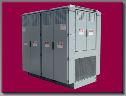
APPLICATION DATA 4USE: This model provides a complete, self-contained system providing the means of meeting NFPA 70, National Electrical Code Standard, Article 700-4 for the exercising and operational support of a standby/emergency generator set. The load bank is typically recommended to be installed outdoors allowing the heat produced to be discharged into the atmosphere. A load bank sized for the "maximum anticipated load" of the facility will provide an optimum maintenance load in accordance with NFPA 70. It also fulfills the exercising requirements of NFPA 99 & 100. Load bank use also prevents "wetstacking." Wetstacking is a condition that can exist in diesel engines when all the fuel is not completely burned and passes into the exhaust system. In Diesel generators, wetstacking usually occurs because the engine is running at only a small percentage of its capacity; therefore the engine does not achieve its optimum operating temperature. Wetstacking may be detectable when there is a black oily residue exiting the exhaust, poor stability of the generator, or when poor generator frequency occurs. Wetstacking can shorten the life expectancy of a diesel generator engine. Utilizing a load bank to supplement the source load (or as the only test load) will help maintain the engine's optimum output rating and will eliminate wetstacking (if the load bank is properly sized). Load banks may also be of necessity for the diesel engine's oxidation catalyst (soot trap) system. Many air quality control districts require these emission reduction systems. In order for the oxidation catalyst system to function properly, the engine exhaust must be maintained at a minimum output temperature. The exhaust temperature must be maintained at the specific minimum level to regenerate the oxidation catalyst system to meet air quality standards. 4INSTALLATION: The load bank is easily installed outdoors in spaces such as rooftops, equipment yards, or other limited access areas. Installation requires a concrete pad or structural framework for mounting. Indoor installation require additional considerations for ducting and static pressure restrictions. The load bank is standardly supplied with a Nema 12 wall mounted Programmable Digital Controller (PDC) for remote mounting in close proximity to the connected source. The Remote PDC Controller requires only a single CAT 5 communication cable for connection and no additional control power if located within 250 feet of the load bank. 4OPERATION: The Programmable Digital Controller (PDC) provides a complete generator operational support system. The controller is programmable for: start-up base loading for load acquisition support, automatic loading/regenerative operation for light and variable loading applications, automatic exercise with alarm monitoring, and basic manual control functions for installation commissioning. 4CONSTRUCTION: The load bank is designed and constructed for a long and reliable life in industrial environments. The load bank is constructed of galvanized steel that is primed & painted using UV Resistant Premium High Performance Acrylic Enamel. The enclosure meets U.L. & Nema construction standards and is standardly provided with lifting eyes, forklift tubes, stainless exterior hardware, and hinged access doors for connection & control compartments. 4RESISTAR® LOAD RESISTOR: The RESISTAR® is designed specifically for high-density applications. The resistor is continuously- supported to minimize shorting contact with surrounding resistors. The resistors are terminated and supported with ceramic components; no plastic or polyester glass laminates are used. They are then mounted in small trays that are easily removed in the field and serviced by a single individual. The RESISTAR® does not require a cool down period and has a standard industry-exclusive 3 year limited warranty. 4COOLING: The load bank is forced-air cooled by (4) direct drive airfoil propellers using (4) TEFC motors with a disconnect and overload relay. These motors contain sealed bearings that do not require lubrication or maintenance during the life of the motors. 4PROTECTIVE CIRCUITS: The load bank is protected with fusing for each load section and control circuit. It is also provided with an airflow and temperature sensor to disconnect the load bank on a failure condition. Voltage and Frequency ranges are also monitored to protect the control power circuits and during alarm exercise failures. |
AUTOMATIC LOADING OPERATION:* The Automatic Loading Operation Function provides the capability to program a minimum loading of the source. This loading reduces inefficient or unstable operation of the source. THE FOLLOWING PARAMETERS ARE PROGRAMMABLE: 4ENABLE / DISABLE 4SOURCE RATING 4PERCENTAGE OF LOAD TO MAINTAIN 4CURRENT TRANSFORMER SIZE 4DELAY PROFILES: INITIAL, LOAD, UNLOAD 4LOADING RESOLUTION |
REGENERATIVE ABSORPTION OPERATION:** The Regenerative Absorption control function provides the capability to absorb load regeneration from sources such as elevators, cranes, etc. to prevent generator overspeed. THE FOLLOWING PARAMETERS ARE PROGRAMMABLE: 4ENABLE / DISABLE 4PERCENTAGE OF REGENERATION |
STANDARD EMBEDDED OPERATIONAL FUNCTIONS & HIGHLIGHTS ALL FUNCTIONS CAN BE ENABLED IN THE FIELD AFTER SHIPMENT & INSTALLATION |
MANUAL LOADING (JOG LOAD) OPERATION: The Manual Operation allows the operator to directly apply desired load to the source (in minimum increments according to load step resolution): 4SELECT LOAD VALUE 4LOAD ON/OFF |
TRANSFER SWITCH INTERFACE: 4A contact interface is provided to indicate the position of the transfer switch to disconnect on loss of utility power. |
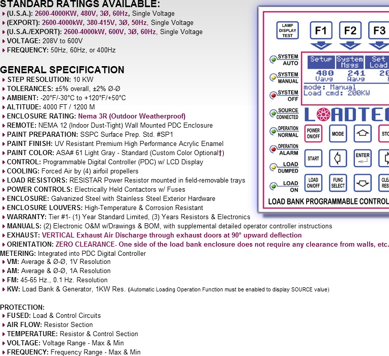
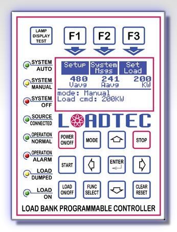
GENERAL PDC STANDARD FEATURES: Features included standard with the Programmable Digital Controller (PDC): 4LCD GRAPHIC OPERATOR DISPLAY 4LED LAMPS FOR SYSTEM STATUS 4REAL TIME CLOCK 4NON-VOLATILE MEMORY SAVES SYSTEM SETTINGS & PARAMETERS 4ABILITY TO CONNECT UP TO (4) ADDITIONAL PDC CONTROLLERS |
BASE LOADING OPERATION: The Base Loading function provides the capability to program the loading of the generator at starting; and before the connection to the facility loads. This capability provides engine turbo boost and alternator field boost to improve generator connection stability to motor load and non-linear loads. THE FOLLOWING PARAMETERS ARE PROGRAMMABLE: 4ENABLE / DISABLE 4VOLTAGE PERCENTAGE INITIATION 4AMOUNT OF LOAD 4TIME LOAD IS APPLIED IN SECONDS |
AUTOMATIC EXERCISE OPERATION:*** The Automatic Exercise function provides the capability to schedule unattended exercising & loading of the source. THE FOLLOWING PARAMETERS ARE PROGRAMMABLE: 4ENABLE / DISABLE 4TIME OF DAY 4DAY INTERVAL/DAY OF WEEK 4TEST SEQUENCE: (8) STAGE 4FAILURE TO COMPLETE EXERCISE ALARM 4Under/Over VOLT & FREQ. LEVELS TO ALARM |
METERING DISPLAYED: The Metering is provided to monitor the electrical values and source loading level. THE FOLLOWING VALUES ARE DISPLAYED: 4GENERAL: VOLTS (VM), AMPS (AM), FREQUENCY (FM) 4LOAD BANK: KILOWATTS (kW) 4SOURCE*: KILOWATTS (kW) (Automatic Loading Operation Function must be enabled to display SOURCE value) |
PROGRAMMABLE DIGITAL CONTROLLER (PDC) CONFIGURATIONS AVAILABLE |
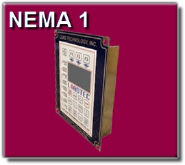
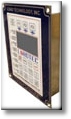
NEMA 1 REMOTE SEMI-FLUSH CONTROL PLATE PDC (PROVIDED LOOSE FOR CABINET MOUNTING) |
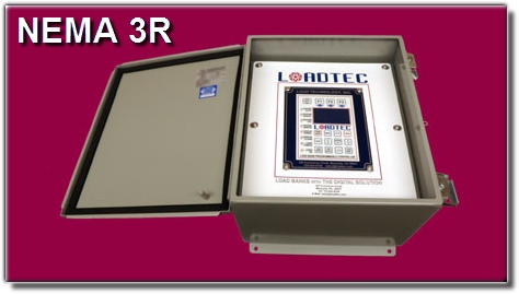
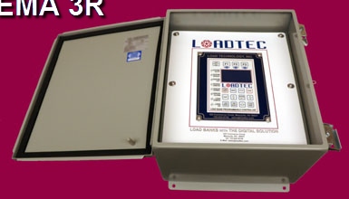
NEMA 3R REMOTE WALL MOUNTED PDC ENCLOSURE (WEATHERPROOF) |
SOUND DATA |
LOADTEC® ADVANTAGE(TM): HIGHLIGHTS STANDARD AND/OR OPTIONAL EQUIPMENT / FEATURES AVAILABLE EXCLUSIVELY WITH LOADTEC® LOAD BANKS |
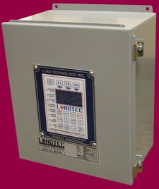


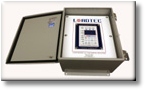


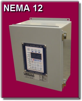
NEMA 12 REMOTE WALL MOUNTED PDC ENCLOSURE (DUST-TIGHT) (STANDARD) |
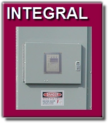
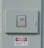
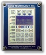
INTEGRAL (LOCALLY-MOUNTED) PDC (MOUNTED BEHIND SMALL WEATHERPROOF HINGED DOOR LOCATED ON LOAD BANK ACCESS DOOR) |
OPTIONAL ITEMS OPTION 1F: NEMA 3R REMOTE WALL MOUNTED PROGRAMMABLE DIGITAL CONTROLLER (PDC) [IN LIEU OF STANDARD NEMA 12 STANDARD REMOTE WALL ENCLOSURE] A NEMA 3R (Outdoor Weatherproof) Wall Mounted Programmable Digital Controller (PDC) is provided as a substitute [in lieu of] for the standard NEMA 12 Remote Wall Mounted Enclosure. ...see more info on NEMA 3R REMOTE PDC OPTION 2F: INTEGRAL (LOCALLY MOUNTED) PROGRAMMABLE DIGITAL CONTROLLER (PDC) [IN LIEU OF STANDARD NEMA 12 REMOTE WALL ENCLOSURE] The Programmable Digital Controller is integrally mounted in the load bank inside a dedicated hinged & gasketed access door connected to a main access door of the enclosure. This integrally-mounted PDC is provided as a subsitute [in lieu of] for the standard NEMA 12 Remote Wall Mounted Enclosure ...see more info on INTEGRAL PDC OPTION 3F: NEMA 1 SEMI-FLUSH "LOOSE" REMOTE PROGRAMMABLE DIGITAL CONTROLLER (PDC) [IN LIEU OF STANDARD NEMA 12 REMOTE WALL ENCLOSURE] A NEMA 1 Semi-Flush Control Plate Programmable Digital Controller (PDC) is provided as a substitute [in lieu of] for the standard NEMA 12 Remote Wall Enclosure. The NEMA 1 semi-flush open configuration provides the PDC "loose" for remote mounting in switchgear or other site cabinetry. ...see more info on NEMA 1 SEMI-FLUSH PDC OPTION 4F: ONE ADDITIONAL REMOTE PROGRAMMABLE DIGITAL CONTROLLER (PDC) [CAPABILITY TO ADD UP TO (4) ADDITIONAL CONTROLLERS] An additional (extra) Remote Programmable Digital Controller (PDC) is provided in addition to the standard NEMA 12 Remote Wall Mounted Programmable Digital Controller. The additional PDC can be added in either NEMA 12 Wall Mounted Enclosure, NEMA 3R Wall Mounted Enclosure, or NEMA 1 Semi-Flush Control Plate "Loose" configuration. OPTION 4 can also be cominbed with OPTION 2 to achieve both an integral (locally) mounted PDC and a remote PDC in either NEMA 1, NEMA 12, or NEMA 3R Remote configurations. OPTION 5F: EXTENDED WARRANTY TERMS In addition to the Standard Tier#1 Warranty supplied with every new load bank at time of shipment, additional extended warranty coverage period tiers are available for purchase up to 5 years from the date of factory shipment. These optional extended warranty tiers are available in PARTS ONLY, and PARTS & LABOR versions. ...see more info on EXTENDED WARRANTY TIERS INFORMATION OPTION 6F: MODBUS SERIAL RTU RS485 INTERFACE FOR PLC, BMS, & SCADA SYSTEMS The MODBUS license for the load bank provides external control of the load bank via Modbus RTU RS485 Serial Interface (interface does not include programming or setup of Master Modbus control device that communicates with the load bank). The Modbus Interface is primarily utilized for integration of BMS, PLC, & SCADA SYSTEMS. ...see more info on MODBUS INTERFACE INFORMATION LOADTEC® is the ONLY load bank manufacturer to offer the ModBus protocol embedded in load banks. OPTION 7F: LOADLINK® WINDOWS® DLL INTERFACE FOR LABVIEW(TM) & WONDERWARE® INTEGRATION The LOADLINK® Windows® DLL Interface License provides an interface for integration into software programs such as LabVIEW(TM) and Wonderware® (programming of system not included). ...see more info on LOADLINK DLL INTERFACE INFORMATION LOADTEC® is the ONLY load bank manufacturer to offer the LabVIEW & WONDERWARE DLL interface embedded in load banks OPTION 8F: LOADVIEW® COMPUTER CONTROL, DATA LOGGING & SCRIPTING SOFTWARE The LOADVIEW® Software is a Windows® PC based control and Data Logging Package. LOADVIEW® Software provides full REMOTE load bank control and data acquisition on a PC based laptop or desktop computer via an RS-232 serial port. Data logging features allow the test to be recorded; reports to be customized, configurated, printed, and also exported to Microsoft Excel®. LOADVIEW® offers the ability to develop customized control screens with sounds, colors, graphics, & metering, all with an unlimited amount of screens to create. Scripting features also allow a customized test profile to be automated and configured to a specific project, jobsite, or customer's requirements. ...see more info on LOADVIEW® SOFTWARE INFORMATION LOADTEC® is the ONLY load bank manufacturer to offer an entire comprehensive software package with these powerful features combined. OPTION 9F: HIGH SPEED RESPONSE (HSR) SOFTWARE MODULE (REQUIRES OPTION 8) The High Speed Response Software Module (HSR) is utilized to determine source (generator) response to block load events captured using high speed data acquisition. The sampling period for the HSR software is 60 cycles pre-event, and 60 seconds of the actual event. Utilizing a logging rate of 8 Khz (1/cycle), the sampling rate is 160/cycle @ 50Hz. The total high speed samples can be displayed and printed in a tabular format or a graph with each value displayed as amplitude versus time. HSR Software is a compliment and additional software function that can be added to the LOADVIEW® Software. ...see more info on HIGH SPEED RESPONSE SOFTWARE LOADTEC® is the ONLY load bank manufacturer to offer a High Speed Response Software Event Capture System for banks. OPTION 10F: TOUCHCOMMAND OPERATOR INTERFACE PANEL (OIP) DIGITAL CONTROLLER SYSTEM [IN LIEU OF PROGRAMMABLE DIGITAL CONTROLLER SYSTEM (PDC)] The TouchCommand OIP Digital Touch Screen Controller system is primarily designed for [and included standard with] our portable load bank product line. However, specific conditions and sites (i.e. data centers) call for the requirements and functions of a more advanced "test module" that fits the capabilities [and is better suited for] of the hand-held Touch Screen Controller System. These special sites require additional functions and operator displays that are included with the TouchCommand system. The TouchCommand system option is offered as a substitute [in lieu of] for the standard Programmable Digital Controller (PDC) system. ...see more info on TOUCHCOMMAND CONTROLLER LOADTEC® is the ONLY load bank manufacturer to offer remote touch screen hand-held controllers for load banks. OPTION 11F: SOUND ATTENUATING BAFFLE Sound Attenuating Baffles are available for effectively reducing the sound dBA level at specific distances of measure. The approximate dBA reduction for LOADTEC® Load Banks at 1M is 15dBA with the sound attentuating baffles option installed (ambient noise must be taken into consideration when sound calculations are performed). The Sound Attenuating Baffle option is provided with a separate exhaust baffle that ships independently of the load bank for field installation (by others). Sound Attenuating Baffles can be installed in the field for specific aging load bank models already installed, however modified louver assemblies must be first retrofitted in the field (by others). ...see more info on SOUND ATTENUATING BAFFLES LOADTEC® is the ONLY load bank manufacturer to offer active sound attenuation solutions for load banks. OPTION 12F: SPECIFICATION COMPLIANCE LOADTEC® offers the availability of creating special and unique custom load bank solutions to meet extraordinary specifications supplied for a particular site or project. LOADTEC's® engineering department will review your specification and advise if we can offer possible solutions to special requirements and/or uncommon requests. LOADTEC® is the ONLY load bank manufacturer to offer the capability to add custom/specific features through software and firmware solutions. |
1-(800)-LOADTEC © 2012 Load Technology, Inc. All Rights Reserved |